DAA Wing Rack
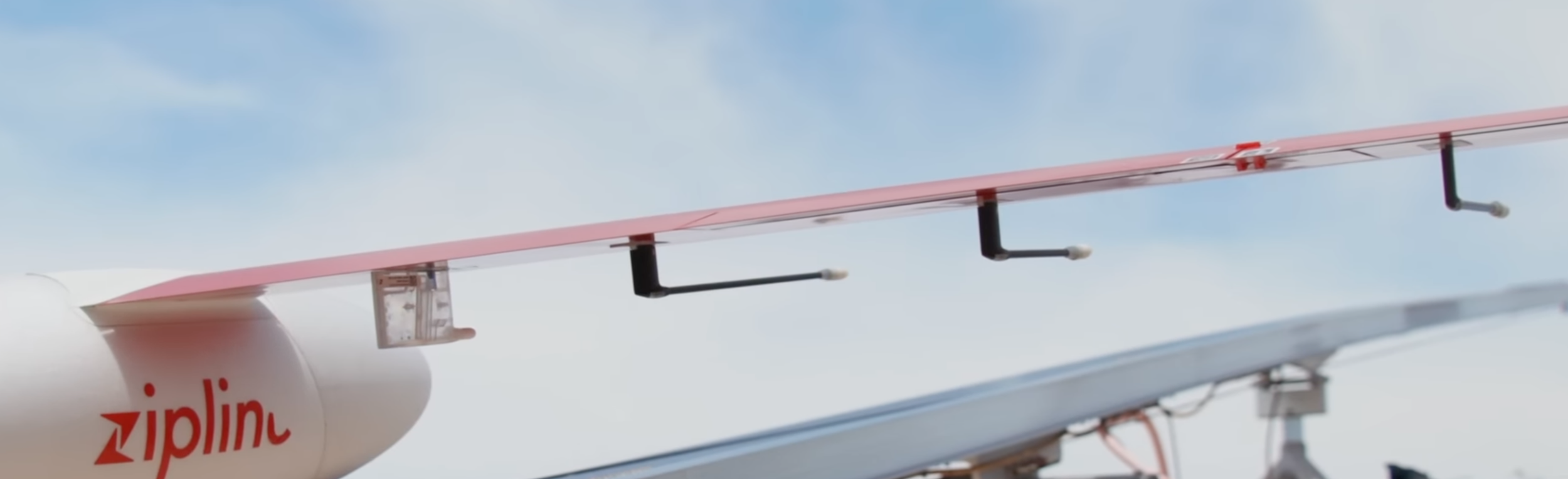
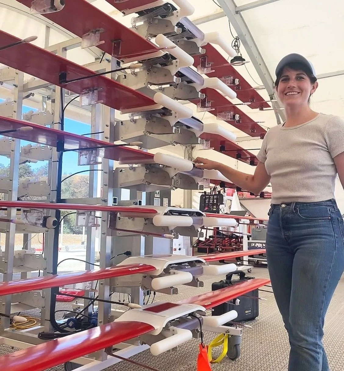
Microphones and cameras were added to the fixed wing drone (Platform 1) for detection and avoidance of obstacles. These new electronics on board needed data offloading over ethernet, thus requiring new ground systems support hardware. I was hired to develop the new electromechanical storage rack.
Rack ergonomics, minimizing operator down-time, and cost drove design criteria (3k units). Electrical component selection, cross-functional requirements path-finding, and blind-mate designs posed exciting challenges. In addition to mechanical design, I owned proto test campaigns, installation documentation, and electrical cabinet design. This assembly was fully released to production.
Zipline, Platform 1
Requirements Pathfinding
-
Confirm WiFi is not sufficient!
Who are my stakeholders? (Ops, ME, EE, Infra) What do they need? What hardware has been locked? UX requirements? Lifetime, serviceability, environments? Cost and shipping limits? What COTS components are available to me?
-
Original UX requirements included matching standard visual indication schemes. The implication was including RGB LEDs on each dock.
Another requirement was not to change wing boards (or connectors) in the scope of rack design.
Keeping Req.2, we only had two pins to play with so we had to get creative. We ended up using wingside probe LEDs for visual indication.
Dock architecture would have been very different with IP-rated electronics! And mirrored probe firmware doubled my minimum floor power requirement; this drove power supply selection and cabinet packaging.
-
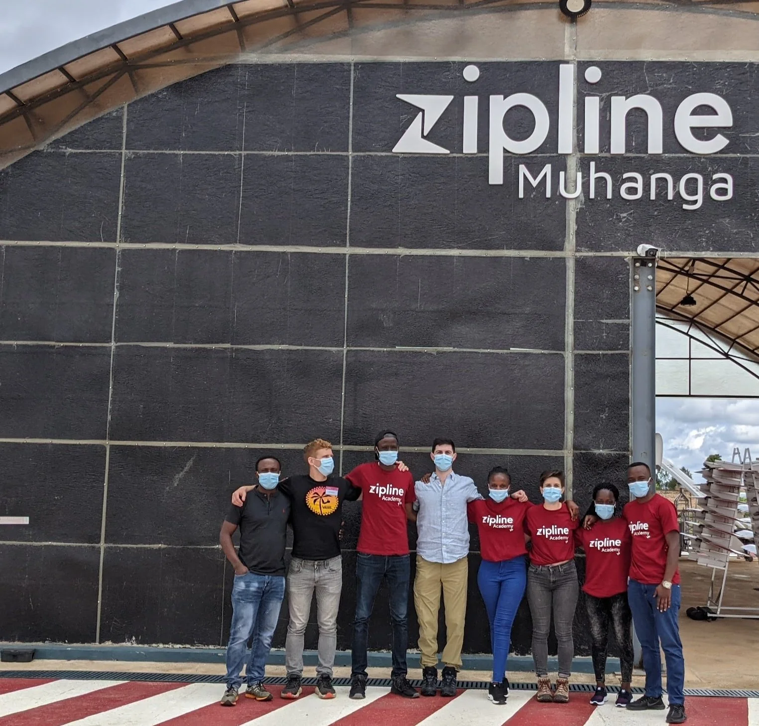
I traveled to Rwanda to understand high volume operations and get operator feedback on what was working well with non-DAA ground systems hardware.
-
Get acquainted with COTS connectors, cables, ethernet switches, power supplies, and cabinets. Include cabinet dimension and rough mass in architectural considerations.
Brainstorming & Prototyping
-
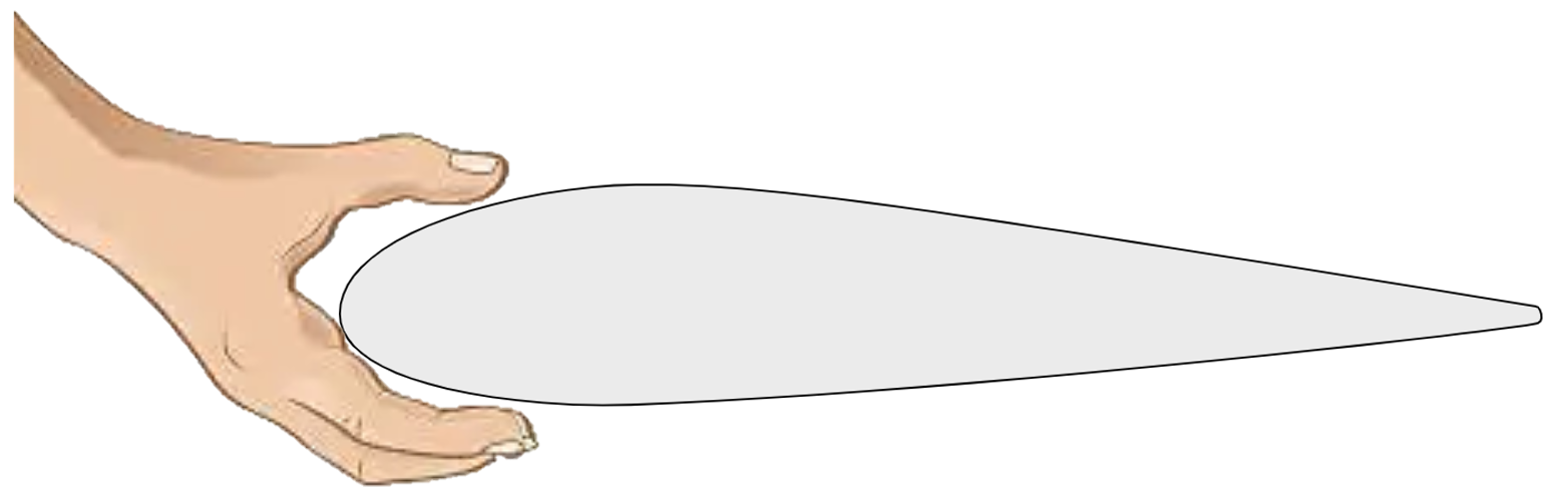
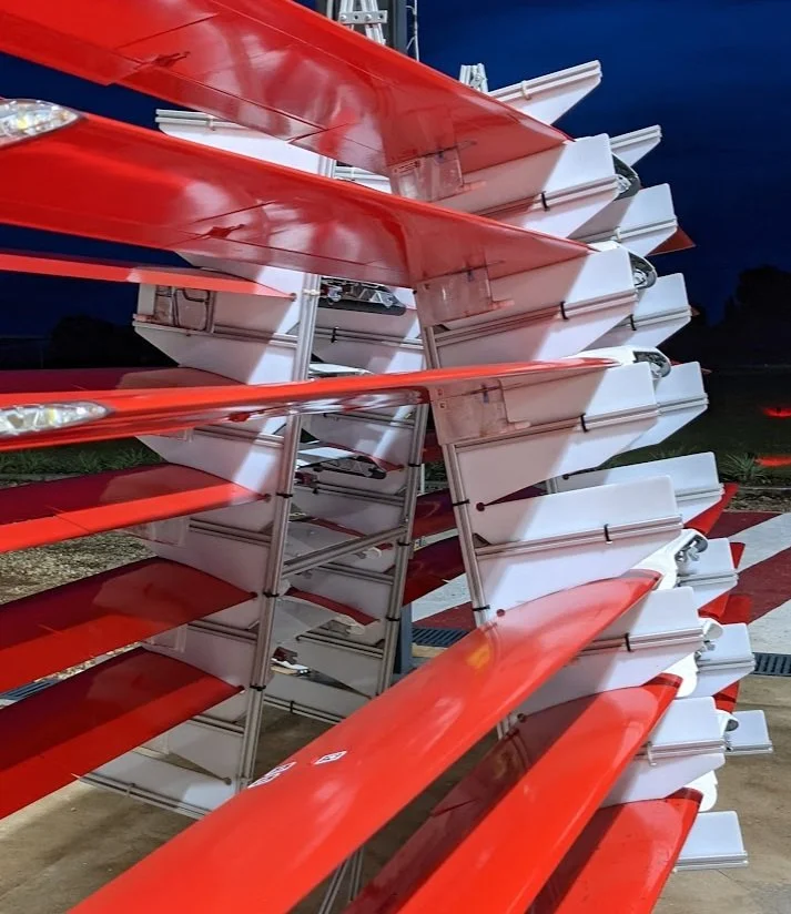
The easiest way to handle wing assemblies (10ft long, airfoil cross-section) is gripping the leading edge with your thumbs on top.
Sideways rotation is out of the question for wing tip damage, and the knife edges on the trailing edge are both fragile and painful to handle.
-
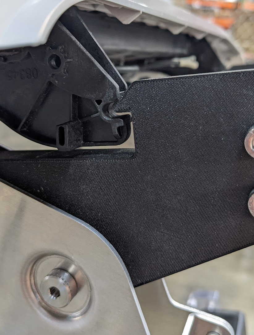
First I tried flexures. In early stage prototypes, I saw lots of deformation and unsuccessful mating after low cycle counts. When connectors started to bind on de-mate, I knew I had to switch it up.
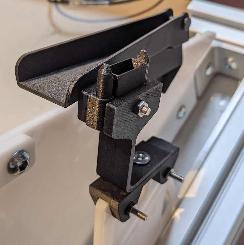
Rotating the wing into a connector housing with rotational float was the most fluid feeling design in proto builds.
-
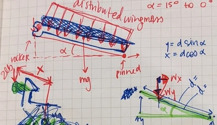
I prioritized minimizing the number of operator actions on “mate,” assuming operators would forget to retain wings if it required extra manual steps.
I decided to try to include wing retention and connector mating in the same motion by incorporating a spring mechanism. I tuned the mechanism to reduce wind-induced wing chatter while optimizing handle and pivot geometry to target ~5lb applied de-mate force.
-
I started getting a feel for relative stiffness changes using lasercut cardboard! The first versions had pivot points in single shear and were really flimsy; the spanner between arm pairs locked the assembly out against parallelogramming.